Case Sharing: High-Speed Hair Dryer Application-The Application of Orient Thyristor Optocoupler and Transistor Optocoupler
As shown in the following picture: High-speed hair dryer

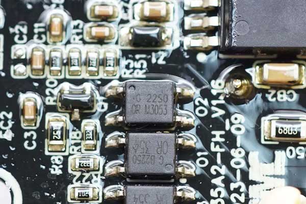
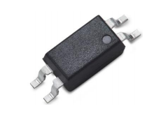
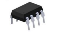
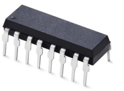
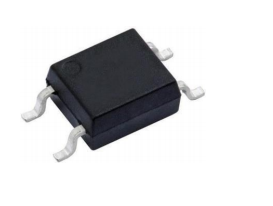
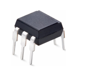
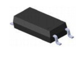
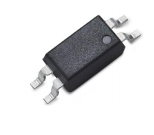
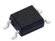
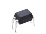
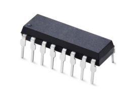
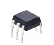
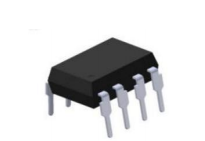
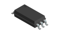
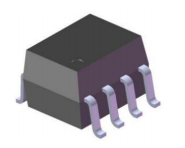
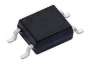
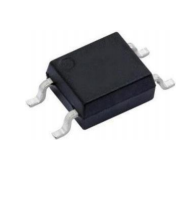
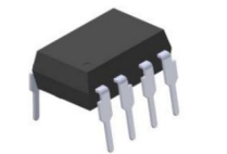
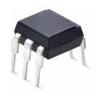
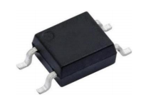
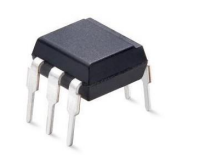
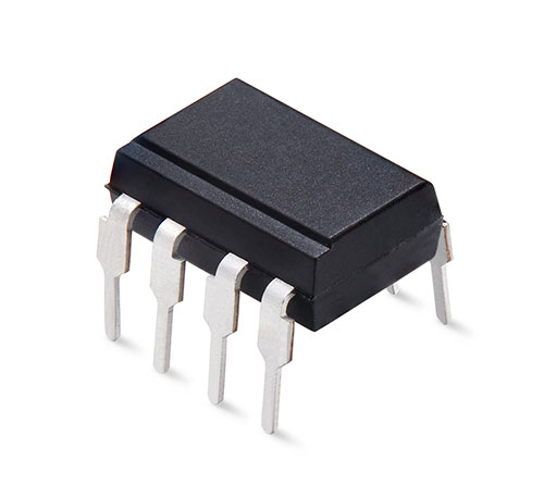
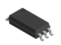
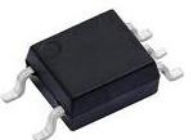
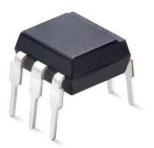
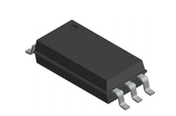
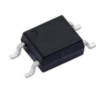
The Orient OR-M3053L-TP-G thyristor output optocoupler is used to drive thyristors,600V IFT 5mA SOP4 package.
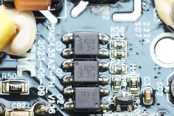
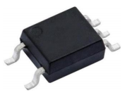
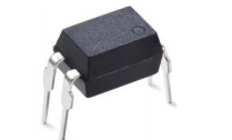
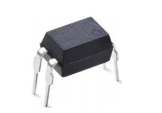
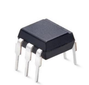
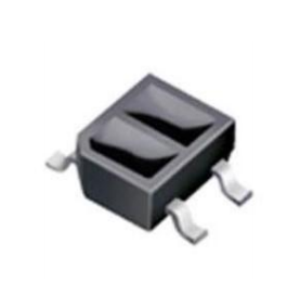
Orient OR-354B-TP-G transistor optocoupler, used for zero-crossing detection and range detection, SOP4 package
Product Introduction of OR-M30XX Orient Thyristor Optocoupler
1.Product List
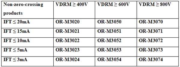
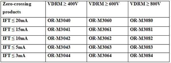
2. Introduction to Electrical Properties
(1)Trigger Current (IFT)
The trigger current (IFT) refers to the minimum current required for IR to conduct when the PT terminal is triggered to turn on. It is an important parameter that needs to be considered when applying customer circuits.
Therefore, when designing, the trigger current provided by the circuit to the thyristor optocoupler must be greater than the IFT of the thyristor optocoupler to ensure that the optocoupler can be triggered and started normally.
a. The influence of temperature on IFT
As shown in Figure 1, the influence of temperature on IFT is that when the temperature keeps rising, IFT will show a slow downward trend within the specification range.
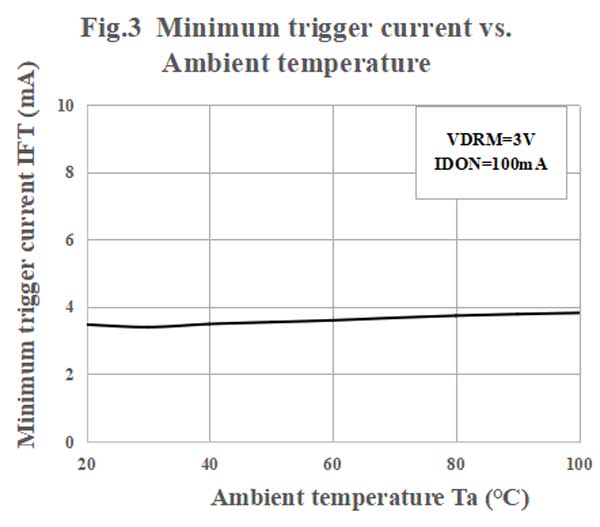
Figure 1: The influence of temperature on IFT
(2). Critical rise rate of off-state voltage (dv/dt)
The critical rise rate of the off-state voltage of the thyristor optocoupler is expressed as follows.
dv/dt=0.63×E1/τ unit V/μS
τ=RW×C unit μS
E1:VDM=2/3VDRM ,RW:Adjustable resistor ,C:Capacitor,used to generate exponential waveforms
From this formula, it can be seen that its dv/dt parameters are mainly important parameters of the PT-terminal thyristor chip itself, which affect the application performance of the optocoupler after packaging.
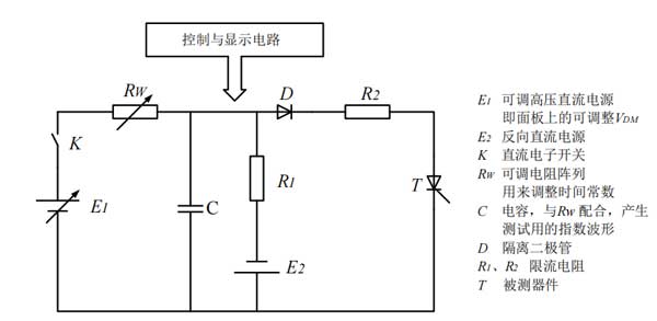
Figure 2 :Schematic diagram of dv/dt testing
(3). Introduction to Other Parameters
① Off-state repetitive peak current IDRM: The forward and reverse peak leakage current passing through PT when the PT terminal is in the blocked state and subjected to the off-state repetitive peak voltage VDRM.
② Blocking repetitive peak current 2IDRM2: In the energized state, when the PT terminal is in the blocked state and is subjected to the off-state repetitive peak voltage VDRM, the forward and reverse peak leakage current through the PT.
③ On-state peak voltage VTM: When the PT terminal is in the conducting state, the voltage passing through PT is called the on-state peak voltage.
④ Holding current IH: The minimum current required to keep the PT terminal in a continuously conducting state after the thyristor optocoupler is turned on.
(4). Circuit Recommendation
Thyristor optocouplers can be isolated for AC load control, provided that the load is relatively small (about 50 mA or less). For larger currents (up to several amperes),
a thyristor optocoupler is combined with a high-power thyristorfor AC load control. The following figure shows the basic circuit configuration. Rs and C are components of the buffer circuit,
which prevent the thyristor optocoupler switch failure by shielding noise, while the varistor absorbs any surge voltage from the powerline.

Figure 3 :Control circuit of a single thyristor optocoupler

Figure 4: Thyristor optocoupler and high-power thyristor control circuit
(5). Application Fields
Small household appliances: hair dryers, health care kettles, dimmable lights, speed-regulating fans, audio systems, toy devices, radio remote controls, etc
Large household appliances: air conditioners, televisions, refrigerators, washing machines, sound and light circuits, timing controllers, cameras and industrial controls, etc
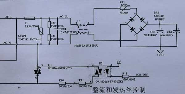
Figure 5: shows the application schematic diagram of the Orient thyristor optocoupler for hair dryer
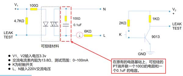
Figure 6 :shows the application principle diagram of the Orient thyristor optocoupler for dimming lamps


